LocoNet testing and measuring
Even with LocoNet you might run into hard to find problems. A module is not responding, commands seem not to get executed or the display of your throttle is flickering. There is a pretty big chance your cable is faulty or your LocoNet is about to run out of power. But how do you find out what is going on? This little tester helps you to locate the problem.
The LocoNet Tester combines three essential functions into one simple board: a cable tester, a connection for a voltmeter and a connection for an ammeter. A handful of readily available parts is all you need to make it work. The parts should only cost you a few euros at a nearby electronics' store. And of course you can buy them over the internet.
| Parts | ||
| Count | Description | Conrad number |
| 4 | resistor 680 Ohm | 1417677 |
| 4 | LED 3 mm | 184713 |
| 1 | pin connector 2x2 | 734246 |
| 2 | jumpers | 734000/742902 |
| 2 | RJ12 connector | 716136 |
| 2 | screw connector with 2 terminals | 729949 |
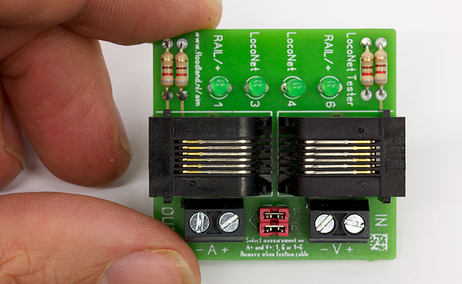
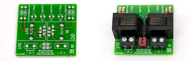
Putting the tester together is pretty straightforward. All components are marked on the board. When soldering the LEDs into place, please keep in mind that the longer leg is the '+'. If you do not have a multi meter, you might as well order one with the components. You will need one to measure Amps and Volts. Cheap meters can even be found at a regular hardware store.
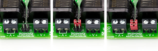
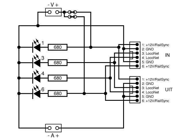
The tester has two terminals for jumpers. In a LocoNet cable, wires 1 and 6 carry the power (refer to The basics of LocoNet for more details on this). By setting the jumpers you can select how wires 1 and 6 of "IN" are connected to both wires 1 and 6 of "OUT". At the "OUT" connector pins 1 and 6 are always connected. The jumpers let you choose what you measure: either one of them or both together. How it all works is explained below.
Testing cables
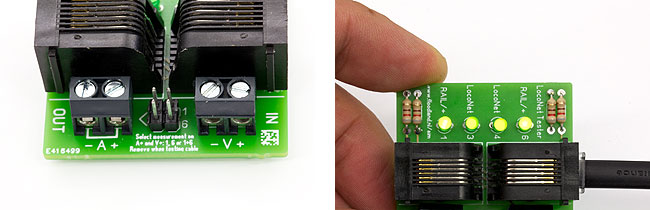
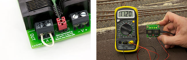
You only use the "IN" connector for testing cables. Please make sure both jumpers are removed as a fault in one of the "+" wires will not be revealed. A small text on the board helps you remember this. Connect one end of the LocoNet cable to the central unit and the other one to the LocoNet Tester. The cable is OK if all four LEDs are on.
Any not lit LED signals a faulty wire. The number and description next to LED help you to identify which wire is causing the problem. Defective cables can best be repaired by crimping new connectors to both ends. Please make sure the connectors are 180 degrees twisted. If both "RAIL/+" LEDs fail to light up, there might be a short circuit in your LocoNet. Disconnect all modules and test all cables starting at the central unit.
Measuring LocoNet voltage (Volts)
Place the jumpers to measure the voltage on wire 1, wire 6 or both wires. Usually you will put both jumpers in place to measure wires 1 and 6 together. Use only one jumper if you are measuring a LocoNet cable carrying the rail sync signal; with both jumpers in place you will shorten the rail sync signal and measure only 0 Volts. If you want to connect a module to "OUT" while measuring, you have to short the "A" terminals with a piece of wire. Connect the voltmeter to "V". Please mind the polarity of the terminals. Net, insert a cable into "IN" and you can read the voltage on your LocoNet.
The voltage should be between +9 and +12 Volts. Is it too low? Use a LocoHubSupply or another Loconet power supply to power (this part of) your LocoNet correctly.
Measuring Loconet power usage (Amps)
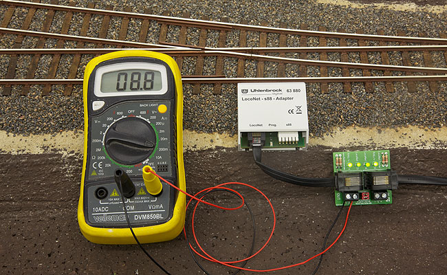
LocoNet has been designed to deliver a maximum of 500 mA. Even on a smaller layout you can reach its limits, which can produce strange errors. For example: some modules might work, others might not or not all the time. If that is the case, you definitely need to measure the power consumption on your LocoNet. Here is how...
Place both jumpers and connect the ammeter to the "A" terminals (or use a correctly set multi meter to do the job). Connect "IN" to the central unit and "OUT" to whatever module you want to measure. Wait about ten seconds after applying power and read the Amps on the ammeter.
Example: an Uhlenbrock feedback decoder uses between 10 and 20 mA, a Profi-Boss throttle about 75 mA and a LocoNet display about 75 mA (measured at 12 Volts).
Build yourself a LocoNet Tester
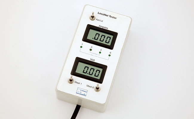
Take this project a step further and turn the board into a all-in-one LocoNet Tester. You only need two simple panel meters, a couple of ON/OFF switches and a plastic housing. Connect a panel meter for Volts and a panel meter for Amps to the boards as outlined above. Replace the jumpers by two ON/OFF switches and lengthen the LEDs with wires so you can mount them in the housing. The LocoNet OUT connector is glued behing a hole in the side of the housing, the LocoNet IN connector is fitted with a LocoNet cable that sticks out at the other end.
Please note: panel meters often need extra resistors to adjust them to the correct Volts (0-19.99) or Amps (0-1.999) range. Please consult the manual of the meters for the details. The best approach is supplying the meters from a seperate battery. You will need a third ON/OFF switch to turn the LocoNet Tester on and off.
The board can be ordered in the shop.
Schematics
2012