Wiring for reversing loops and wyes
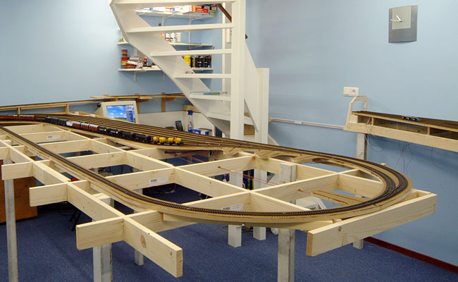
Reversing loops and wyes are found on many layouts. For example, to turn a train in a staging yard. Märklinists can lay down loops to their heart's content thanks to the 3-rail system. On a 2-rail layout, however, there is a bit more to it.
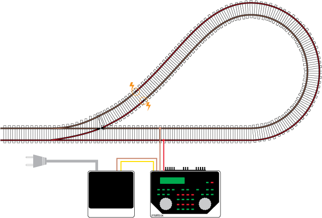
What's the problem? The left and right rails come together in a reversing loop, causing a short circuit. The short circuit can be prevented by double insulating the rails at both ends of the loop.
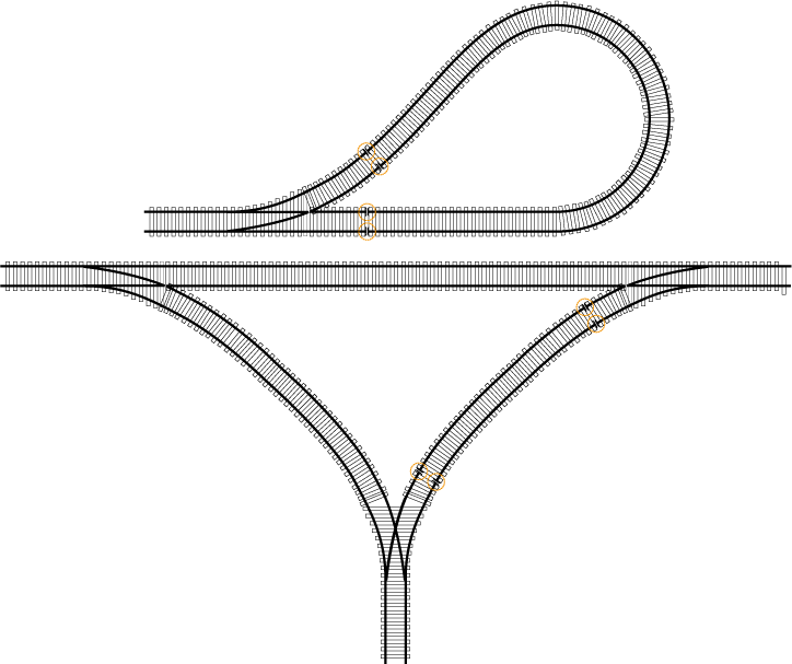
A wye has the same problem as a reversing loop. One of the legs of the wye should be insulated at both ends. You connect the insulated leg in the same way as the loop of the reversing loop
The analog solution
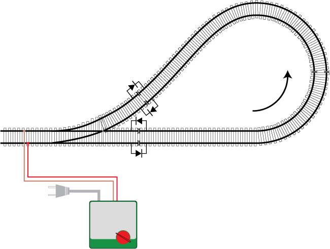
When a train passes through the loop, the voltage of the insulated track must be reversed. Only then can the train travel over the insulations without a short circuit. In the analog era, four diodes were used for this. The train entered the loop, the dial on the transformer was reversed and the train exited the loop again.
On a digital layout there is no DC voltage, but a square-wave AC voltage on the rails. Unfortunately, the trick with diodes no longer works. As you will see, this requires a completely different approach. In the analog solution, the rest of the track is reversed by turning the dial on the transformer, while on a digital layout, the polarity in the reversing loop is reversed. An analog locomotive will change direction when the polarity is reversed; a digital locomotive just drives on.
Using short circuit detection
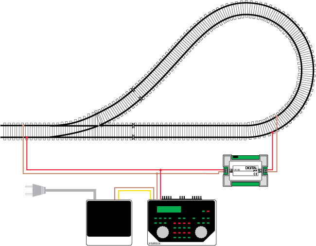
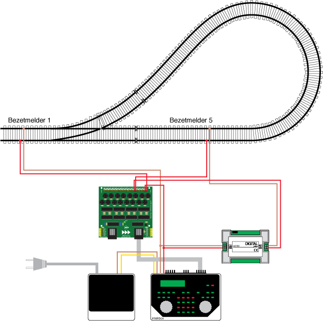
The simplest solution is to use a reversing loop module with short-circuit detection, such as the LK100 and LK200 from Lenz. The loop is double insulated on both sides and supplied with voltage via the module. The insulated part of the loop should be long enough to accommodate the longest train. On one insulation the polarity is correct, on the other it is not. When a train runs over the insulation that causes a short circuit, the module reacts by quickly reversing the voltage in the loop. The locomotive decoder is not bothered by this and the train continues uninterrupted.
The advantage of this method is the easy connection. There are also drawbacks. The sensitivity of the modules is sometimes difficult to adjust. Because the module itself also uses power, any feedback decoder must be placed between the rails and the reverse loop module. Not all feedback decoders, such as the 63320 from Uhlenbrock, still work when the voltage is reversed.
Using a booster
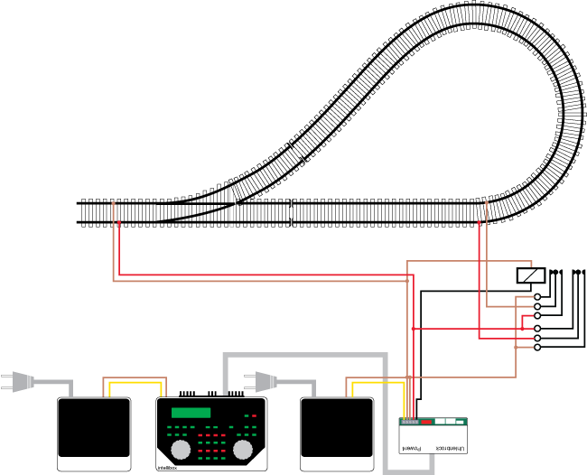
Some boosters, such as Uhlenbrock's Power4, have a special provision for reversing loops. Each booster has a circuit for short circuit detection and the same circuit is now used for the reversing loop. As soon as the booster detects a short circuit, it switches an external relay. The relay again reverses the voltage in the reversing loop. If the short circuit persists, the booster switches off.
The external relay is sold as an expensive accessory, but you can just as well use a separate monostable relay with two double contacts. The coil must be suitable for 12 to 16 Volts DC. For a few euros you have an excellent solution for your reversing loop, which works better than most separate reversing loop modules.
Using extra detection sections (track contacts)
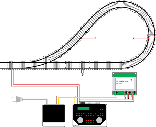
It can also be done differently, with additional detection sections. The sections detect when a train is approaching an isolation. The module reverses the voltage before the train passes the insulation. A short circuit never occurs and that is considered an advantage. On the other hand, you have to add extra sections to your track and the circuit is more complex. LDT 's KSM-SG is an examples of such reversing loop modules-with-extra-detection-bits.
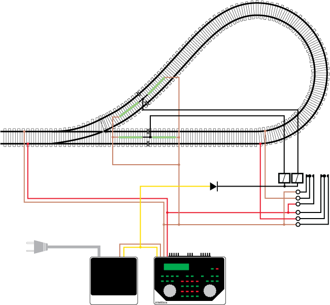
Using an IR detector (light barrier)
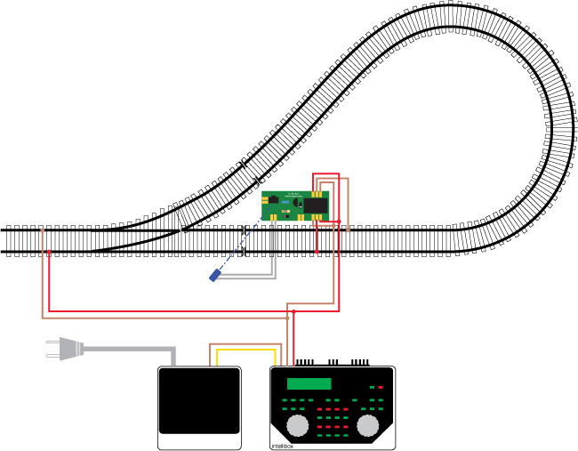
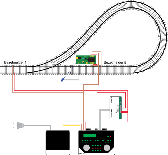
The third solution uses an IR detector or light barrier. The reversing loop must again be double insulated at both ends. The light barrier is installed diagonally over one of the insulations. The relay of the light barrier reverses the voltage in the reversing loop. By default, the polarization is correct for the insulation without a light barrier, so that the train can drive over the insulation without a short circuit.
When the train approaches the isolation with light barrier, the light barrier will see the train before it reaches the isolation. The light barrier reverses the polarity of the reversing loop, so that the train can travel over the insulation without a short circuit. As soon as the train has cleared the light barrier and the insulation, the relay will return to its default position and the next train can come. The reversing loop can be traveled in both directions.
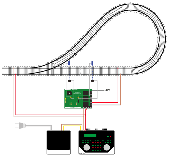
Using a light barrier on both ends
You can also use two light barriers, one for each insulation. The light barriers switch an extra (bistable) relay that reverses the polarity. The additional diode is only required if the relay coils operate on DC voltage.
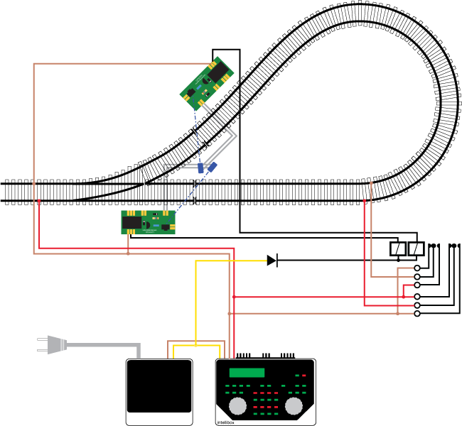
Using an Arduino and two light barriers
The idea of the light barrier can be solved more elegantly with an Arduino. The Arduino reverses the polarity of the reverse loop via a relay as soon as a train passes one of the light barriers. A programmed release delay prevents the relay from rattling.
Using reeds or contact tracks
The voltage reversal relay can also be operated with reed contacts or contact tracks. The reversing loop can be driven in both directions if there is a reed contact or contact track on both sides of each insulation. If the loop is only driven in one direction, one contact for each insulation is sufficient. The reed contact or the contact track switches the relay to the right position just before the locomotive passes the insulation.
This solution is easy to build with standard model railway parts and completely short-circuit-free. Reed contacts have the disadvantage that each locomotive must be fitted with a magnet. Trains need a magnet at both ends. If you don't use reed contacts, contact tracks may be a more convenient choice.
Using a turnout
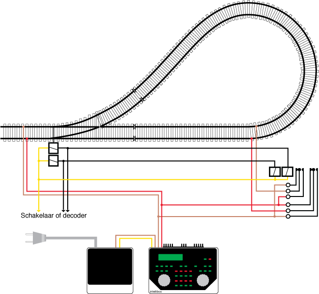
Yet another possibility is to switch the voltage in the reversing loop when the turnout is thrown. For this purpose, a relay is connected in parallel to the turnouts coils or motor. Imagine... the switch is set to straight ahead. The relay is connected in such a way that the train can drive straight over the insulation. When the train is halfway through the turning loop, the switch is thrown. The polarity in the loop reverses and the train moves out of the loop without a short circuit.
Train (current) detection in a reversing loop
Train detection in a reversing can be a bit problematic. Ideally, a feedback decoder with current detection is connected between the loop module and the reversing loop. The reversing loop modules from Lenz, among others, consume digital power to operate and would generate a permanent detection if the feedback decoder is placed between the loop module and the track.
The big advantage is that you can install different occupancy detectors in the reverse loop, while you only need one reverse loop module. The BMD16N-SD was specially designed for this. If you build the strip connector variant, you can use some of the inputs for your reversing loop, while the other inputs remain available for the rest of the track.
Some feedback decoders cannot handle reversing the polarity. For example, the 63320 from Uhlenbrock. The only solution is to connect the feedback decoder between the power source and the reversing loop circuit. You cannot use such a feedback decoder with a reversing loop module that consumes digital current itself.
If you have several occupancy detectors in the reversing loop, you will have to use a separate relay for each occupancy detector. In the example with the light barrier, the additional relays are simply connected in parallel with the relay of the light barrier. The same goes for the booster with an extra relay, for the solution with the reed contacts and for the polarity reversal via the switch. In reversing loop modules with additional detection sections, the multiple feedback is usually resolved via the reversing loop module. This is explained in detail in the manufacturer's manual.
2011