Interesting IR detector
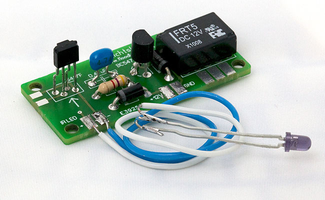
An IR detector is ideally suited to detect trains, especially if there is little margin for error or where other detection methods are hard to implement. Sharp’s IS471F IC comes with almost all the circuitry you need to build a reliable IR detector. Just add an IR LED, a relay and a handful of components and you can switch on and off about everything. The reach of the detector is about 30 cm. By using the LD 274 IR LED this can extended to about 1 m. Of course you can use other IR LEDs as well; the wavelength should be in the 900-980 nm range.
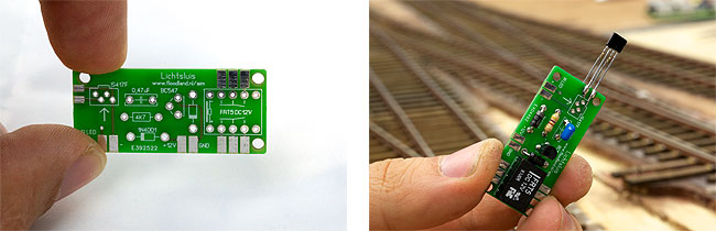
I have designed a compact circuit board for the IR detector. It can fit almost between the tracks almost everywhere. You can also mount the detector IC on the short side of the board. This gives you the option to mount the board under the layout and stick the detector through a hole besides the track. The LED is connected to the board via wires; it is mounted on the other side of the track.
| Parts | |||
| Count | Description | Conrad # | Reichelt # |
| 1 | Sharp IS471F | -- | -- |
| 1 | IR LED 940 nm | 171140 | LD 274-3 |
| 1 | transistor BC547B | 1262957 | BC 547B |
| 2 | diode 1N4001 | 162213 | 1N 4001 |
| 1 | resistor 4,7 kilo Ohm | 1417695 | 1/4W 4,7K |
| 1 | capacitor 0,47 µF | 453374 | Z5U-5 470N |
| 1 | relay FRT5 12V DC | 504394 | FRT5 DC12V |
Check this overview for the parts too.
The table lists the part numbers for Conrad and Reichelt; they seem to have discontinued the IS471F. The IS471F is available from other shops. Alternative sources are Farnell (part nr. 9707840) and eBay. Or just use Google to find a local supplier.
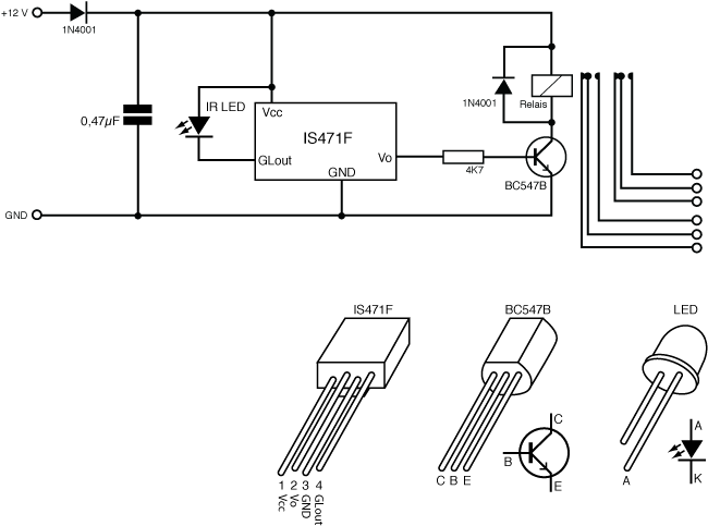
You will need a few components besides the IS471F to make the detector work. The detector works on 12 Volts DC. A diode makes sure nothing burns up if the power supply is connected adversely. If you don’t have a stabilised 12 Volts DC power supply lingering around, you can create one easily with the 78xx power supply board. The output of the IS471F drives a transistor, which drives a relay. The relay has two sets of switching contacts, which caters for a wide variety of applications.
Connecting
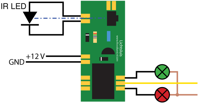
Connecting the IR detector is straightforward. Solder the LED to the two pads next to the detector IC and connect the power. Aim the LED at the flat side of the detector. When you move a hand between LED and detector, you should hear the relay switch on and off. You can connect just about everything (check the data sheet for maximum ratings if you intend to do extreme stuff). For example: a set of lights that indicate whether something is blocking the detector. This is how you make a train detection for your (analogue or digital) staging yard, control the lights at a railroad crossing or .... well, whatever you want.
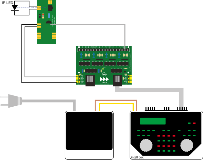
With BMD16N and BMD16N-SD feedback decoders
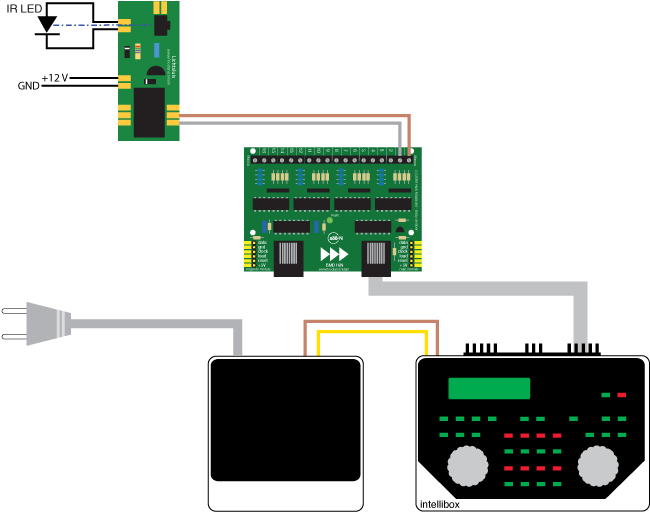
Of course you can connect the IR detector to a feedback decoder as well. In this example I used the BMD16N. The IR detector delivers a more accurate detection than the traditional ground detection or current detection techniques. If you use a computer to control your trains, you can make them stop exactly on the spot, i.e. over a decoupler.
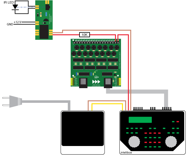
You might as well combine the detector with a BMD16N-SD current feedback decoder. You only need to add a simple 10 kilo Ohm resistor to make it work.
Automating reversing loops
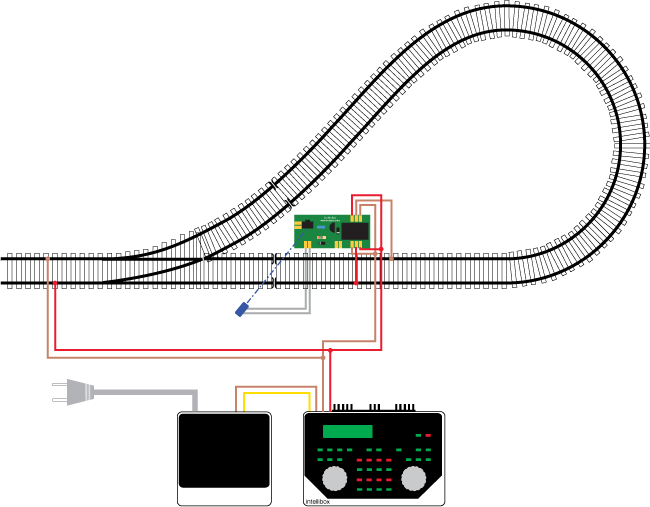
The IR detector also provides a simple and reliable reversing loop solution, which is not based on short circuit detection (like most reversing loop solutions are). The reversing loop has to have double isolations on both ends. Mount the IR detector next to the track and make sure its beam crosses one of the isolations diagonally. The relay of the IR detector is used to reverse the polarity of the reversing loop. By default the polarity should be alright for crossing the isolation at the other end of the loop.
A train can enter at the other end without any problems. When the train approaches the IR detector, its beam catches the train before it reaches the isolation near the detector. The detector flips the polarity and the train can pass the isolation. When the train has passed the IR detector and the isolation, the relay is released and everything resets to the default state. The reversing loop can be travelled in both directions.
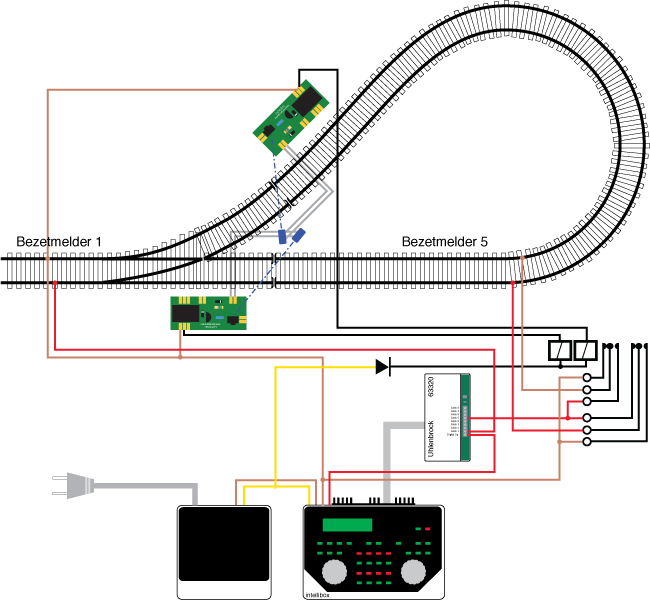
A more complex solution can be created with two IR detectors. The detectors switch an extra relay, which in turn controls the polarity of the reversing loop. The feedback decoder has nothing to do with the actual reversing loop circuit, but illustrates how you can add current detection to a reversing loop. You can use the same set-up to add detection to the single IR detector reversing loop solution above.
For experts: without relay and with BMD16N
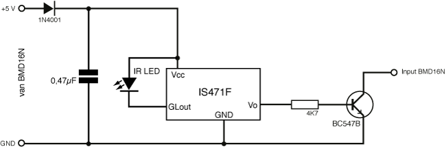
The IR detector can also be connected directly to the input of a BMD16N without using a relay. We take advantage of the fact that the core of the circuit also works on +5 Volts. The IR Detector is connected to the power of the S88-bus through the terminals on the side of the BMD16N. The collector of the transistor is connected to one of the inputs. Both the diode and the relay can be left out.
Boards are available from the shop.
Please note: some versions of the board accidentally refer to IS417. The correct part number is IS471F/FE.
2011