Reversing loop with Arduino
There has been a lot of discussion about the reversing loop problem in digital 2-rail model railways. A solution without short circuits is the best. In practice this comes down to several occupancy detectors / detection sections that reverse the polarity of the reversing loop via a relay before the train reaches one of the insulations. The disadvantage of this approach is that you often need four detection sections with all the wiring that goes with it.
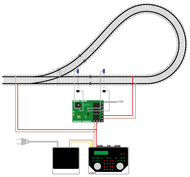
I believe there is an easier way to solving this problem. On Buitenlust I used two light barriers to solve the wye loop problem in the track plan. With a cheap Arduino clone, two light barriers and a handful of other parts you have the ultimate solution within reach. Without short circuits and with minimal wiring.
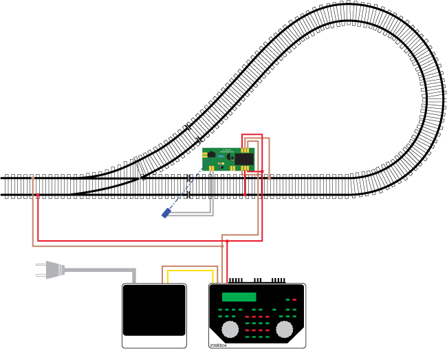
How does it work? The reversing loop is double insulated at both ends. Let's call these insulations ISO1 and ISO2. The light barriers are located to the left and right of ISO2. The distance between them is smaller than the shortest locomotive or carriage. The reversing loop is connected in such a way that the polarity is correct for ISO1 by default. As soon as and as long as one of the light barriers is occupied, the Arduino reverses the polarity in the reversing loop via a relay. The train can now drive over ISO2 without a short circuit. Only when both light barriers are free for an adjustable number of seconds does the polarity return to the starting position. The reversing loop can be traversed in both directions.


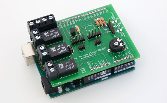
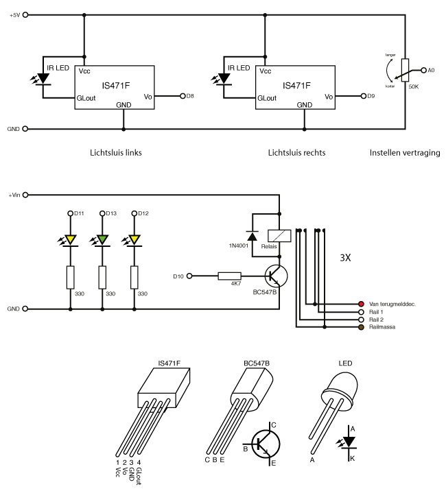
For the circuit I made a simple Arduino shield. Instead of one relay there are three on it, so that you can divide the reversing loop into a maximum of three occupancy detectors if desired. The three relays are controlled in parallel and switch at the same time. The drop-out delay can be set via a potentiometer. The shield is simply clicked onto the Arduino. Connect the wires and you're done.
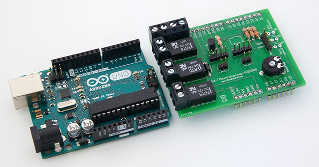
The circuit has only a few components. The light barriers consist of an IS471 with IR LED. The output of the detector is directly connected to an input of the Arduino. The potentiometer is used to set the drop-out delay and is connected to an analog input.
| Parts | ||
| Count | Description | Reichelt # |
| 3 | Resistor 330 Ohm | 1/4W 330 |
| 1 | Resistor 4,7 kilo Ohm | 1/4W 4,7K |
| 1 | PT10 50K | PT 10-L 50K |
| 1 | Transistor BC547B | BC 547B |
| 1 | Diode 1N4001 | 1N 4001 |
| 2 | LED yellow 3 mm | LED 3MM GE |
| 1 | LED green 3 mm | LED 3MM GN |
| 2 | IR LED | LD 274-3 |
| 3 | Relay FRT5 12V DC | FRT5 DC12V |
| 5 | Connector screw terminal | AKL 101-02 |
| 2 | IS471FE | Webshop Magica Miniatura |
| 1 | Arduino shield | Webshop Magica Miniatura |
| 1 | Set stackable shield headers | Webshop Magica Miniatura |
| Print connectors | Your choice | |
| 1 | Arduino Uno | |
Three LEDs indicate the status: the green LED lights up when the circuit is active. It starts flashing as soon as the delay is running. The yellow LEDs indicate for which isolation the polarity is correct. The left one is for ISO1, the right one for ISO2. The relays are controlled simultaneously via a transistor and a suppressor diode. The Arduino is supplied with +12 Volt, which is also the voltage for the relays. The voltage stabilizer on the Arduino turns that into +5 Volt for the processor.

The IR detectors and IR LEDs are connected to the print with cables. The status LEDs can be mounted directly to the PCB, but I have extended them with a cable to the front of the layout.

This is how it works... Imagine that the yellow strip of tape is ISO2. The left yellow LED is on: the polarity is correct for ISO1 (out of the picture here). The train approaches the light barrier. As soon as it passes the light barrier, the Arduino reverses the voltage for ISO2. Now the other yellow LED is on.

When passing ISO2, one of the light barriers is always occupied. The polarity remains reversed. After the train has passed, the green LED starts flashing. After the delay has elapsed, the relay drops back. The polarity is now correct for the other crossing, ISO1. The reversing loop can be traversed in both directions.
A short video of the passing of the light barriers. You can clearly see the polarity flipping as the train enters and leaves the light barrier.
The shield, the IS471F and the stackable shield headers are available in the Magica Miniatura shop.
2015 - 2024