The basics of LocoNet

LocoNet was developed by Digitrax. It has been adopted by several other manufacturers over the years, in Europe notably by Uhlenbrock. You will find LocoNet on the Uhlenbrock Intellibox, the Fleischmann Twin-Center and the Piko Digi-Power-Box. The great thing about LocoNet is that all modules attached to it know what all the other modules are doing. For example: a layout plan track control will display occupied tracks and a signal will react to a Lissy module, without the central unit having to arrange it.
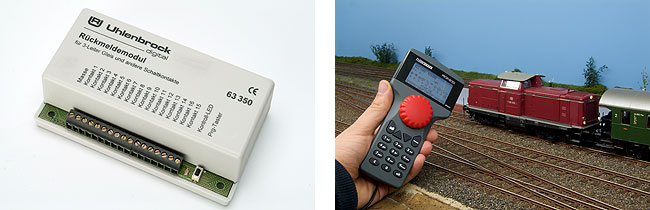
LocoNet is probably the most widespread of all digital ecosystems, especially in the US. That means there is a lot to choose when it comes to accessories. Uhlenbrock offers a wide range of equipment from feedback decoders to boosters. Bigger accessories like the Track Control track plan and the IB-Control are connected via LocoNet too. Digitrax also offers quite a catalogue of stuff, including throttles and power management. Many smaller manufacturers produce LocoNet compatible products as well.
Connecting to LocoNet
LocoNet uses standard American phone line wiring. The cables have six wires, which is two more than you will find in Europe. The outer ones (1 and 6) carry the raildata signal from the central unit. The signal is meant to drive boosters connected to the LocoNet. The wires can allso carry +12V DC. The inner wires (3 and 4) carry the actual LocoNet signal. The other two (2 and 5) are the signal ground. The signal on wire 3 equals the signal on wire 4; 2 equals 5. The official name for the plugs is RJ12. You can by them from e.g. Conrad.
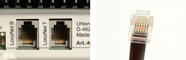
The Intellibox has two LocoNet connections. LocoNet B is intended for connecting boosters, but you can also use it for other LocoNet equipment. LocoNet T is for throttles, decoders and other LocoNet accessories. You cannot connect a booster to the LocoNet T terminal; pin 1 and 6 provide 12 Volts DC, instead of the railsync signal the booster needs. LocoNet B has a maximum output of 200mA, LocoNet T can deliver 500mA.
Building the network
A LocoNet network has no fixed topography. You can connect equipment anywhere you want. The network can branch out almost endlessly using splitters and connector boxes. A LocoNet network can be up several hundreds meters long. Even at those lengths LocoNet is a very reliable network.
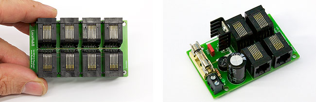
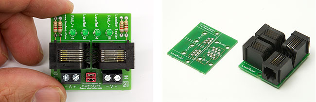
You are free to choose any network-layout you want, but you should never create a loop. Digitrax advises against it, because it can cause interference in the network. Any other layout (tree, star, etc.) is fine. In the end, the limiting factor is the available power on the LocoNet-bus. The central unit only delivers 500mA and if you connect too many modules that will not be enough. To overcome this problem you can split the network up into sections and use a LocoNet booster, like the LocoHubSupply, to power the extra sections.
Making cables
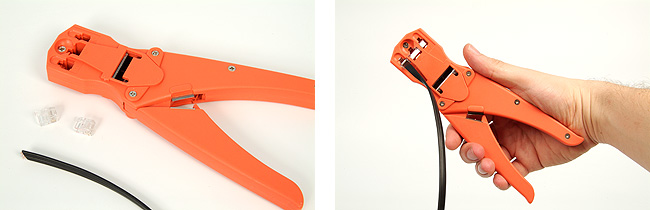
It is not hard to make LocoNet cables yourself. You will need just one tool: a crimper. Any crimper will do, as long as it is suited for 6p6c cables. Start by stripping the ends of the cable with the blade on the crimper. The wires should be sticking out about one centimetre. Do NOT strip the six wires, but leave the plastic mantle on. Push the wires parallel into the RJ12 plug and stick the plug into the crimper. Now press the crimper together to push the pins in the plug firmly into the wires.
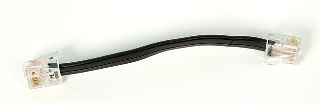
The plugs on the cable should be 180 degrees twisted. The wire being connected to pin one on one side should also be connected to pin one on the other side. An improperly made cable will cause problems when you are connecting a booster. The signal on wire 1 is the opposite of the signal on wire 6. If you switched the wires you will have also switched the polarity of the track signal from the booster. A short-circuit will appear when a train is transferring from one booster to the next. To cut a long story short: always use cables with twisted plugs.
More LocoNet:
Expand your Loconet the easy way with the LocoHub →
LocoHubSupply, add more power to your LocoNet →
LocoNet testing and measuring →
2008, 2010, 2011, 2012