BMD16N-SD and BMD16N-SD XL
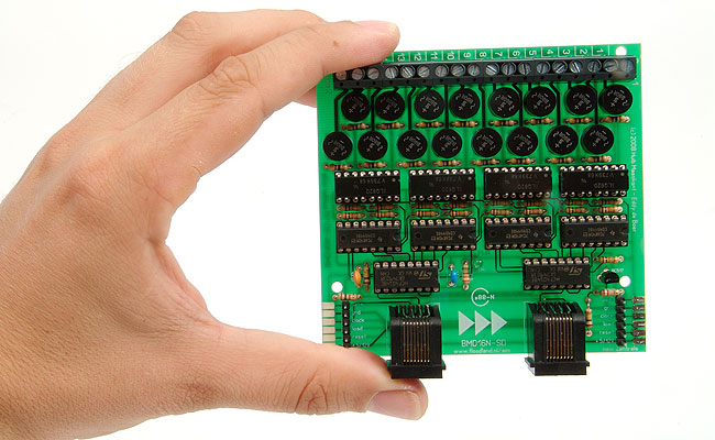
The BMD16N-SD is a feedback decoder with integrated current sensing for the S88-bus. The s88-bus can be connected via network cables to greatly reduce the risk of errors. The BMD16N-SD is just like the BMD16N fully compatible with the s88-N standard. The board has been developed in dialogue with one the initiators of s88-N, Wolfgang Kufer. More information on s88-N can be found on his website. Or take a look at s88-N.eu.
The integrated current sensing makes the BMD16N-SD very suited for providing feedback on 2-rail layouts. The BMD16N-SD can be used with any S88 based system, for example Märklin Digital, the Uhlenbrock Intellibox, the ESU ECoS and the LDT HSI-88. Thanks to its s88-N connectors, the BMD16N-SD can be connected to all other equipment bearing the s88-N logo.
The BMD16N-SD XL

The BMD16N-SD XL is the bigger brother of the BMD16N-SD. This decoder is designed for occupancy detection using current sensing, specifically for larger scales such as gauge 0 and 1. Just like the BMD16N-SD, the BMD16N-SD XL is compatible with any command station featuring an S88 or S88-N connection. In the BMD16N-SD XL, the inputs are always grouped into two sets of eight. Apart from that, the BMD16N-SD XL is connected in the same way as the standard BMD16N-SD.
BMD16N-SD advantages
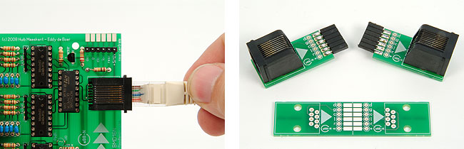
The BMD16N-SD has number of interesting features. The decoder has 16 independent contacts. Each contact has its own input and output. That is twice the number of contacts compared to most other decoders. The BMD16N-SD is connected via standard S88 cables or UTP network cables. Network cables are much cheaper and are less sensitive to electrical interference. You can use cables that are over 5 metres long without a problem.
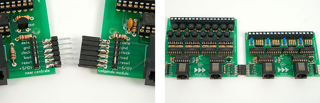
If you mount several BMD16N-SDs and/or BMD16Ns directly next to each other, a simple print connector or a few wires is all you need to connect the decoders. That will save you cables and money. The BMD16N also features an improved reset circuit. This eliminates possible errors even further.
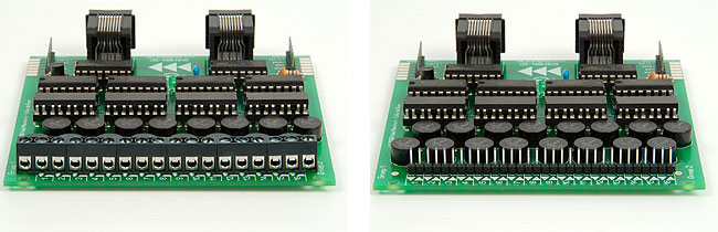
You can decide yourself how you want to configure the 16 contacts: in two groups of 8, as 16 independent contacts or any combination of the above. You can also choose whether you want to fit your board with inexpensive strip connectors or sturdy screw connectors (only if you configure your board as two groups of 8 contacts).
Getting the parts and building the decoder
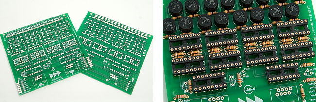
The BMD16N-SD and BMD16N-SD XL are do-it-yourself projects. The professional boards are being produced in a top facility. You can order them in the shop of Magica Miniatura. Please consult the extensive manual for the part list.
You do not have to be a soldering virtuoso to assemble a BMD16N-SD, but some experience is advisable. The manual will guide you through the assembly step by step. The rectifiers on the board are suited for any H0 scale layout or smaller. They will also work in O scale, unless you are operating locomotives with really big power-consuming engines. In that case I would recommend replacing the rectifiers with bigger ones.
Connecting to S88 and s88-N

The feedback decoders are connected to the central unit as a chain. The order of the decoders determines how the contacts are numbered. The first decoder has contacts 1 to 16, the second one 17 to 32, etc. You can connect up to 31 decoders with 16 contacts to the S88-bus.
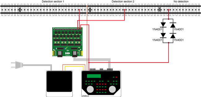
Connecting the tracks

The BMD16N-SD is typically inserted in the red wire running from the central unit or the booster to the track. The wire connects the input of the decoder with the output of the central unit or the booster. A second wires connects the output of the decoder with the right rail. The left rail is connected directly with the central unit or the booster via a brown or a black wire. You use a different contact for each feedback section (occupancy detector). The BMD16N-SD allows you to connect each contact to another power source.
Sections without detection
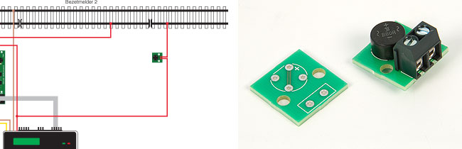
Sections without detection are connected via four diodes. If you want to do it professionally you can use the additional voltage reduction board. The rectifier bridge on the board creates the same small voltage difference as the BMD16N-SD does. The parts are: rectifier B80C1500 (501441) and 2-pole screw connector (729949). This ensures proper detection if a train enters a section with detection from a section without detection. This is a recommended practice not only with the BMD16N-SD, but with all decoders using current sensing.
Reversing loops

The option to connect each contact to another power source comes in handy with e.g. a reversing loop. The reversing loop module has to be connected between the central unit and the feedback decoder. The module uses some power itself and if yo were to insert between the feedback decoder and the rails, the decoder would signal the track as ‘occupied’. The inputs of the contacts inside the reversing loop (which can be as many as you want) are simply connected to the reversing loop module. The outputs are connected to the track.
Märklin C and M track
If you are building a Märklin layout, your best option is a BMD16N with ground detection. However, it can be hard to isolate one rail from the other with C track; with the old M tracks it is outright impossible. In such cases you could opt for current sensing and a BMD16N-SD. You simply put the section dividers in the centre rail rather than in the right rail. There is one little but... only locomotives and cars with a pick-up shoe - track power users - will be detected.
Testing
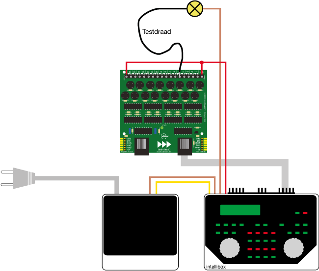
The BMD16N-SD and BMD16N-SD XL can be tested with a few wires and a light bulb or LED (+ 1K5 resistor). Connect the decoder to the S88-bus of your central unit and call up the menu that displays the status of the feedback decoders. Connect the feeder terminal of the central unit with the group terminals of the decoder. Connect another wire to the ground terminal and attach the light bulb to it. Touch each of the outputs with a wire that's connected to the other side of the light bulb. At each output, the light bulb should light up and the feedback status should change to occupied.
Boards are available from the shop at Magica Miniatura.
2008, 2012, 2018, 2025
BMD16N-SD Features
Integrated feed back decoder with 16 contacts with current sensing for the S88-bus
Suited for all 2-rail model railroads, gauge 0 to Z
Also perfect for Märklin C and M track
Compatible with a.o. Märklin Digital, Uhlenbrock Intellibox, ESU ECoS and LDT HSI-88
Compatible with the s88-N standard and all other s88-N equipment
Connect the S88-bus via standard S88 cables or reliable network cables
Other BMD16N/BMD16N-SD decoders can be directly connected sideways
Even further reduced risk of errors thanks to improved reset circuit
Contacts can be configured in 2 groups of 8, 16 independent contacts or any combination of the above
Choice between inexpensive print connectors or sturdy screw connectors
Easy to assemble for everyone with some soldering experience
Extensive manual with step by step assembly plan
Already thousands in use around the world
Download
View or download the manual.