Universal module connector
Buitenlust is in contrast to Project Waldberg and De Lage Zij a completely modular layout. Or to be more precise: it is made up of several segments, because they are not standard 0 gauge modules. Several electrical connections have to be made between the segments. Of course you can make your own cables with connectors for that, but I was looking for a standard solution that was practical as well as not too expensive.
MC25
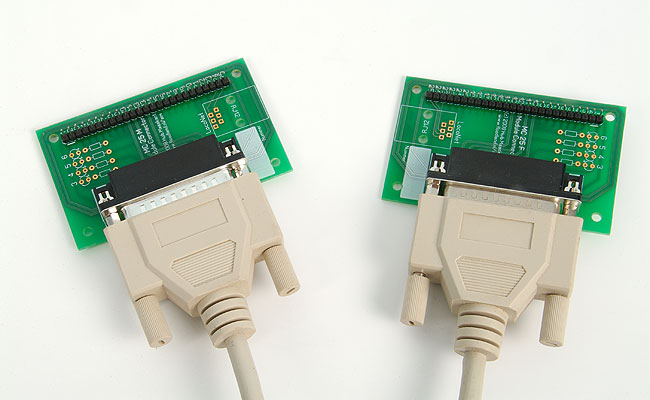
The universal module connector uses standard printer or serial computer cables. You can buy these cables everywhere in any length for pretty low prices. The cables have 25 wires, which is well enough to connect the segments of a modular layout. I have special circuit boards made to facilitate connecting the cables. The boards are mounted under the layout, which gives you a rigid point to connect the cables to. Another advantage is that you can now solder the connecting wires to a big strip connector instead of the small pins of the normal 25-pole connector.
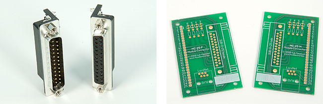
The cables have a male connector side and a female connector on the other side. That is why you need two different circuit boards with two different connectors. The connectors can be ordered from Conrad Electronics: 741452 for the male version and 741819 for the female version. Conrad can also supply the cables. Look under computer serial cables and be sure to pick one that has the pins 1:1 connected. The part numbers at Reichelt are W+P 107-25-1-1-0 and W+P 107-25-2-1-0.
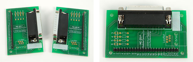
Assembling the boards is a breeze. Just stick the connectors in the designated holes and solder the pins to the board. The strip connector can also be ordered from Conrad as part number 741119 or as SL 1X36G 2,54 from Reichelt. I connected pins 1 and 2 on the boards. They are intended for the central ground of your layout. All return current will flow through it, so it seemed a good idea to use two wires for it. You still have 23 wires left for connecting tracks, lights and other stuff.
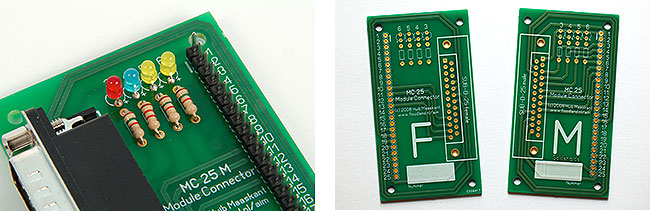
I am often using the first four wires (3 to 6) for various power supplies, such as track power, power for lights, etc. So I reserved space on the boards to add four LEDs that will light up if the power is connected. These are all options. You don’t have to use them. But I like to think it makes the connector boards pretty universal.
Please note: In 2013, the two seperate boards were replaced by a single board with the female and male connector on either side. The LocoNet option is NOT included on the new generation boards.
The MC25Box
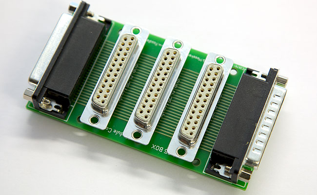
When I was connecting several groups of modules, it seemed a good idea to develop some sort of power strip to distribute power and signals. And so I did. The MC25Box has a male connector on one side, a female connector on the other side and three more female connectors in the middle. You can add several together with cables to form a central power bus. The extra connectors let you connect (goups of) modules to it. The wiring becomes very clear and easy to assemble.
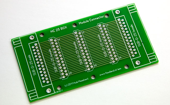
You can order the connctors from Conrad: the male on the left is part number 741452, the female on the right is 741819. The connectors in the middle are 742638 (or else 746034).
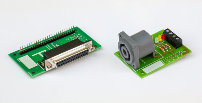
MCCON4
The heavy O Gauge models at Buitenlust require more power than the thin wires in the printer cables are intended for. That is why I have developed the second universal module connector based on Speakon connectors. The professional loudspeaker connectors can handle much heavier loads and are extremely rugged. Speakon connectors are available with two, four and eight contacts; however, the latter are quite rare. In the Netherlands, the Speakon connectors are relatively expensive. In China they cost less than a euro, including shipping.
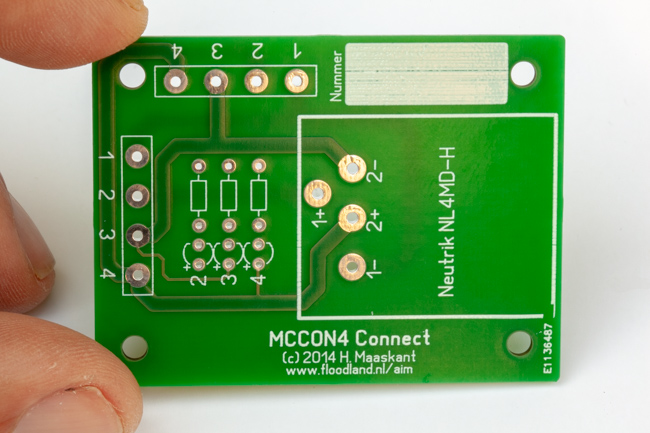
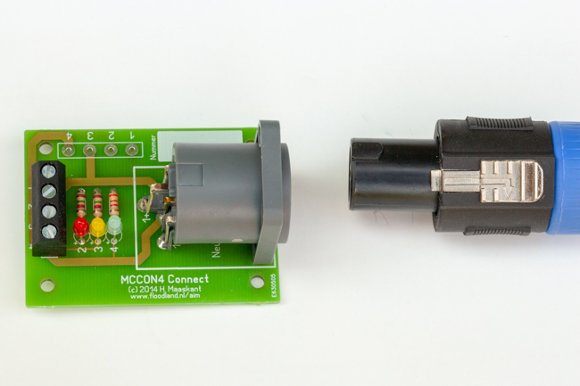
There are Speakon connectors with screw terminals. In most cases these will do the job perfectly. I wanted to add LEDs, so that I can immediately see whether a module group receives the required voltages. A simple PCB offers space for a Speakon connector for PCB mounting, three LEDs, three resistors and two blocks with screw terminals.
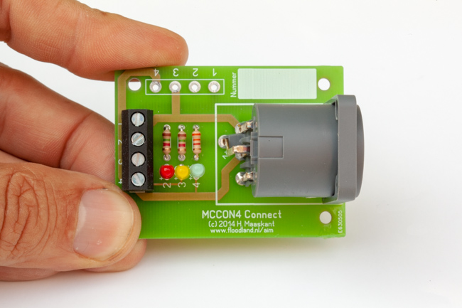
I use the Speakons at Buitenlust to connect the central modules of a module group to the power supply. The other modules are connected to the central module with 25-pin cables. The three LEDs indicate the status of the three main supply voltages: the digital voltage from the control panel or booster, 16 Volts AC and 12 Vols AC. You can, of course, organize it differently.
Boards are available from the shop.
2008, 2011, 2013, 2019