Braking module Märklin Motorola
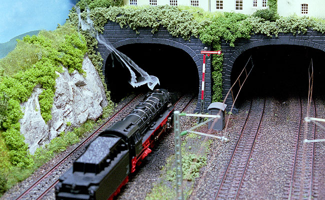
Modern Märklin locos stop abruptly in front of a red signal. These locomotives are equipped with a DC motor with a permanent magnetic field, which has a strong braking effect. Long time ago Märklin introduced a module for smooth braking: signal module 72441. The signal module offers an electronic solution for the problem. The module is rather expensive when you consider that the components inside are quite cheap. Fortunately it is easy to build such a module yourself.
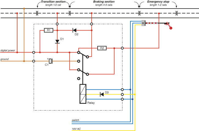
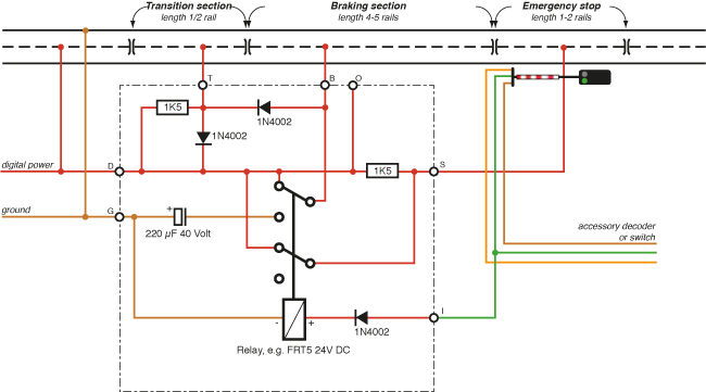
The track is divided in three isolated sections. The middle section is the longest and is called the braking section. Locos with a high performance decoder/engine brake slowly when they detect a negative DC voltage. This is exactly what happens in the braking section. The functions of the locos remain turned on, including smoke unit and sound.
The transition section is only there to prevent a short-circuit between the braking section and the rest of the layout. The third section provides an emergency stop for locos that pass the signal. When the signal turns to green the loco accelerates to its original speed.
Locos with an old-fashioned c80/c81/DELTA decoder will stop at the beginning of the braking section (as tested with different makes of these decoders). Some locos keep their function ON (lights remain on), while others have their function OFF. Please note: as long as a loco is stopped in front of a red signal, it cannot receive any commands from the Control Unit.
| Lengths | |
| Transition section: | 9 cm (1/2 rail) |
| Braking section: | 90 cm (5 rails) |
| Emergency stop: | 18 cm (1 rail) |
Build it yourself on veroboard
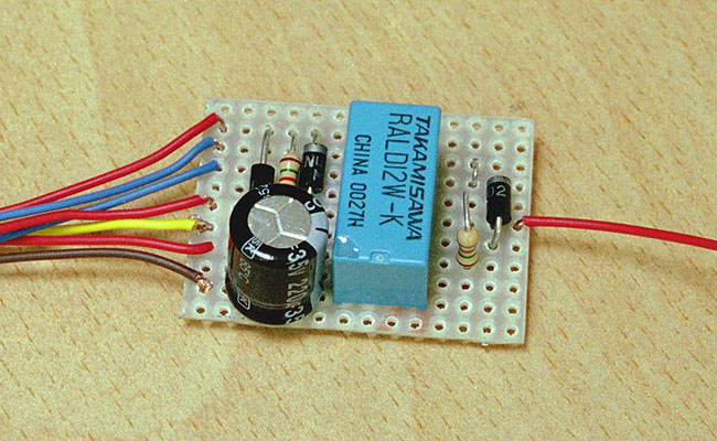
The circuit can easily be built on a small piece of circuit board. I used a little piece of striped board of 11 strips by 14 holes. The layout of the board will vary, depending on the relay you are using. Please regard the board I made as an example and design your own version.
Please pay attention to the correct direction of the various components. Do not forget to make cuts in the strips as indicated. You can buy the parts at any electronics shop or order them from Conrad or Reichelt.
| Parts | |
| Part | Value |
| Circuit board | Standard board |
| R1, R2 | 1.5 K Ohm |
| D1, D2, D3 | 1N4002 |
| C1: | 220 µF 40 Volt |
| Relay | 2 x switch, bistable, 24 Volt |
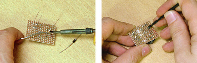
The module can easily be put together with a small soldering iron. Do not forget the small wire connection to the right of the relay. The easiest way to cut the strips is by using a 5 mm drill.
| Connections | |
| • Transition section | • |
| • To green (from decoder/swith) | • |
| • To red (from decoder/switch) | • |
| • | • |
| • Braking section | Emergency stop section • |
| • 16 V AC | • |
| • Digital power (red) | • |
| • | • |
| • Ground (brown) | • |
This is what the finished module looks like. The direction of D3 depends on how you connect
the module to your layout. If the relay does not work, you have to flip D3. Now connect it
to the layout and brake away!
Alternative for light signals
Simple light signals come without a relay or any other means of control. Adding a seconde relay to the braking module lets you control them via a standard switch decoder or toggle switch.
Solution with a simple monostable relay
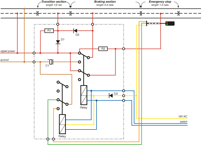
Bistable relays are notoriously hard to come by (especially in the digital age). Can you use a standard monostable relay instead? Yes, you can! A straightforward solution is to use the signal's track output. You can find these contacts on e.g. Viessmann signals and the old Märklin semaphores. The contact is now used to switch on the braking module, which in turn makes the trains stop and go. Please note: the relay is drawn in the activated position here.
Monostable relay without a signal
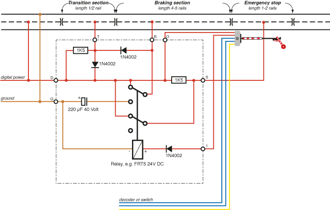
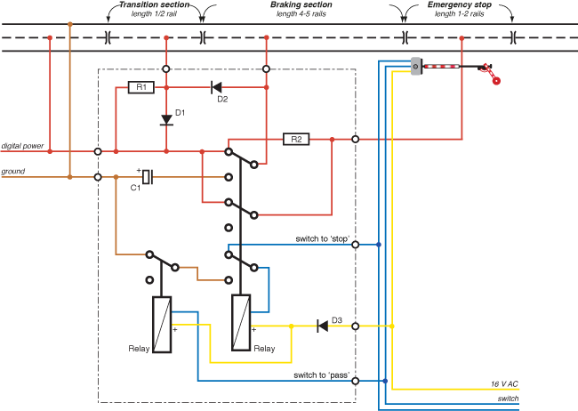
You don't need an expensive semaphore to make this idea work; you can also comntrol the braking module through an accessory decoder or a simple switch. You'll need a decoder that can deliver permanent power, rather than just a pulse like a switch decoder. The classic Märklin K84 is such a decoder, but also LDT's SA-DEC-4 and there are many more. Modern decoders allow you to program the outputs to either permanent or pulse. Of course you can use these decoders too. Please note: the relay is drawn in the activated position here.
Monostable relay with a light signal
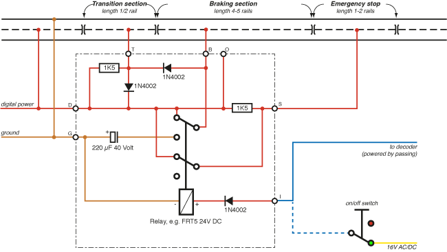
Building on the previous schematic, you can add a light signal to it. The signal is controlled directly by the accessory decoder (or a switch). The relay of the braking module follows the lights of the signal. Again, the relay activates on green. The easiest way to make this work is to use a common cathode signal. Please note: the relay is drawn in the activated position here.
Monostable latching relay
Here is a classic solution to a classic problem: using two monostable relays to create a bistable one. This is called a 'latched' relay, as the relay latches itself in the hold position until it is released by a short power-cut from the other relay.
2001, 2016