Dutch semaphores
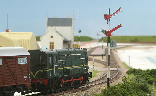
De Lage Zij has a classic signalling system on the branch line to Magerveen. Unfortunately you cannot buy good-looking Dutch semaphores in the shops. So the obvious way to go is to build them yourself. Philotrain sells etched semaphore arms in brass. You ‘only’ need to make the poles and the actuators.
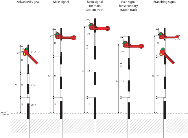
The classical Dutch signalling system is quite complex. Gerard van de Weerd describes the system in great detail on his – Dutch – website. On De Lage Zij I confined myself to the simple semaphores with a single pole. On main lines one could find very complex constructions with several semaphores combines into one signal. These are quite hard to model and would be out of place on a branch line like mine. De drawing represents the most common signal in H0 scale.
Magerveen station has four departure signals of equal length. This layout was used for stations with a maximum speed of 40 km/h. The entrance to station is secured on both sides by a branching signal with advanced signal. Officially a branching signal has to be preceded by a special advanced signal with two arms and separate colour shifter. This signal is quite hard to make as a model, so I put a normal advanced signal there instead.
The pole
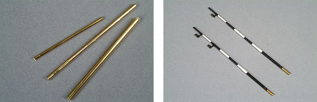
The first step is assembling the pole. It consists of two brass tubes of 2.5 mm en 2.0 mm and a brass rod of 1.5 mm. The inside of the tubes is drilled to a bigger diameter, so the three parts will fit together. After soldering the joints, the pole is ready.
The lamp fitting is piece of brass tubing with a diameter of 2.0 mm. The inside is drilled to a diameter of 1.5 mm. This is just wide enough to accommodate a micro light bulb. A perpendicular 1.5 mm hole allows the light out in the right direction. The lamp fitting is soldered to the pole with a small brass strip. The distance between the light source and the centre of rotation is critical. The hole in the lamp fitting has to be exactly behind the coloured glasses in the arm.
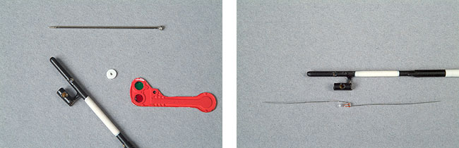
The arm is attached to the pole after all parts have been spray painted in the right colours. A common pin makes a good axle. The pin is inserted from the front and fastened with super glue. A plastic disk goes between the arm and the pole to make sure there is enough distance between them. I made the disk from sheet styrene with a pair of punch pliers. I used the same pair of pliers to punch the coloured glasses from plastic sheet.
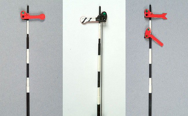
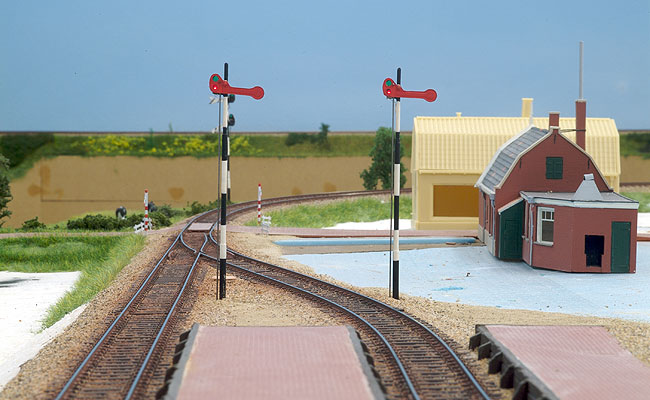
The finished signals. A normal main signal has a red arm with a rounded tip. The rear side is black and white with two diagonal black lines in the white part. The black lines are best made with a thin black marker. The branching signal stands out with its fork-shaped arm. The lower part of the arm has not been painted white yet.
The actuators
Making the signal is one thing, constructing the actuator is a different matter. Since the points with memory wire work pretty well, I decided to use the same material to get the semaphores to move.
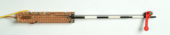
The actuator is build to show red as the default position. A current through the wire makes it contract. The movement of the wire is enlarged by the little leaver at the bottom. The metal rod is pulled downwards and the signal moves to green. When the power is cut, the wire relaxes and the spring pulls the signal back to its red position.
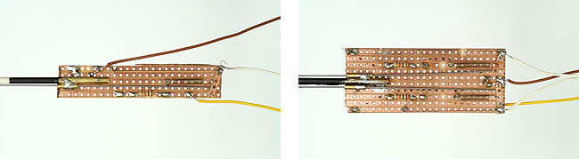
A single actuator is enough for the simple signals. The branching signals have two arms and therefore require two actuators. They fit nicely together on one circuit board. The resistors have little to do with the actuators; they provide the correct voltage for the light bulbs in the signals.
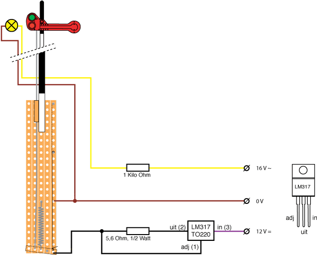
Just a handful of electronic components is enough to make the signals work. The actuator is powered with 12 V DC. The LM317 confines the current to just over 200 mA. The IC gets pretty warm and needs a cooler to prevent it from getting too hot. The light bulb is connected to 16V AC via a resistor.
2006